
Overview
Mission
Instrument Concepts
MOPITT is a nadir sounding instrument, which provides a horizontal resolution of 22 km, but introduces a number of challenges, such as the need for acurately characterizing the surface contribution to the signal.
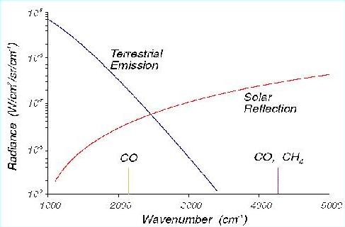
Figure: MOPITT operates by sensing infrared radiation from either
the thermal emission/absorption at 4.7 µm for CO profiles, or reflected
sunlight at about 2.2-2.4 µm for CO and CH4 column
measurements in daylight. The use of solar channels enhances
the instrument sensitivity to the atmospheric boundary layer.
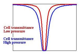
MOPITT uses correlation radiometry for the detection of CO and CH4.
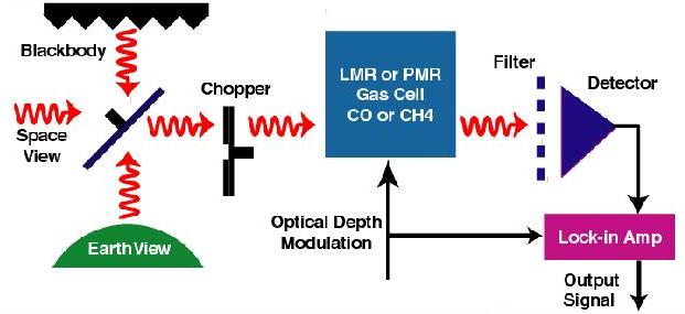
Figure: Signals pass through a cell containing the
target gas, CO or CH4. The cell pressure or length is varied,
which produces a modulation in cell opacity within the lines of the target
gas, while the cell opacity at other frequencies remains constant.
MOPITT has both pressure-modulated and length-modulated cells
Pressure Modulated Radiometer (PMR):
- Operates by changing the cell gas pressure using a piston
- Advantages:
- Few moving parts
- Disadvantages:
- Complex pressure and temperature cycles
- Upper pressure is limited
- Used to increase instrument sensitivity to the upper troposphere
Length Modulated Radiometer (LMR):
- Being used for the first time on MOPITT
- Operates by changing the gas path thus modulating the gas amount
- Achieved by rotating a disk of calcium fluoride in the vacuum cell
- Advantages:
- Pressure/temperature/time behavior is simple
- Pressures can be higher than PMRs
- Disadvantages:
- Optical components are moved in addition to cell gas leading to potential "imbalances"
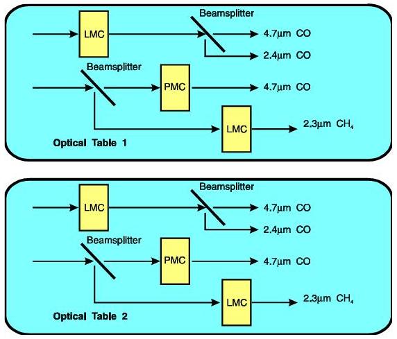
MOPITT has 8 channels laid out on 2 optical benches.
| Channel # | Primary Purpose |
Modulator Type |
Cell Pressure (mb) |
Cell Temperature (K) |
Cell Length (mm) |
Spectral Band | Center Wavenumber (cm-1) |
|---|---|---|---|---|---|---|---|
|
|
CO | LMC1 |
|
300 |
|
CO thermal | 2166 (52) |
|
|
CO | LMC1 |
|
300 |
|
CO solar | 4285 (40) |
|
|
CO | PMC1 |
|
300 |
|
CO thermal | 2166 (52) |
|
|
CH4 | LMC2 |
|
300 |
|
CH4 solar | 4430 (140) |
| 5 | CO | LMC3 |
|
300 |
|
CO thermal | 2166 (52) |
| 6 | CO | LMC3 |
|
300 |
|
CO solar | 4285 (40) |
| 7 | CO | PMC2 |
|
300 |
|
CO thermal | 2166 (52) |
| 8 | CH4 | LMC4 |
|
300 |
|
CH4 solar | 4430 (140) |
 |
The high and low opacity signals from each channel are both averaged and differenced, resulting in 8 D and 8 A signals. |
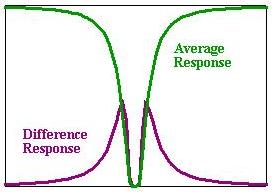 |
Average signals are low at the line of interest,
providing information about background radiance and interfering signals.
Difference signals have only significant response at the line of interest, providing information about the gas of interest. |
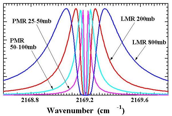 |
The correlation cell pressure determines the portion of the pressure-broadened line wing that is sampled. |
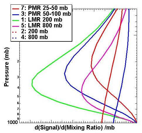 |
Using PMRs and LMRs with different pressures thus provides
information about the vertical profile.
These are the weighting functions for the different cell pressures of the 6 CO channels. |
MOPITT diagrams and photos
Schematic
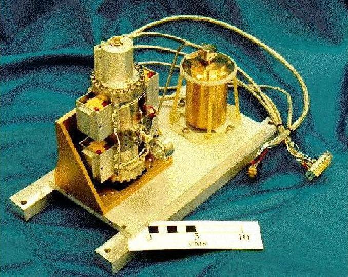
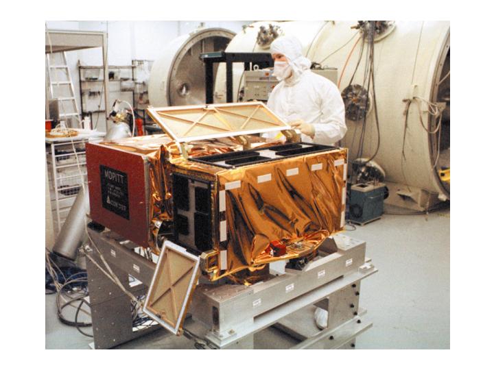
Photo
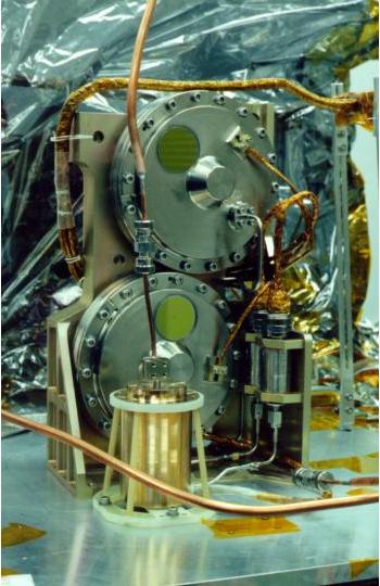
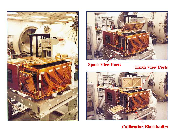
Photo indicating calibration sources
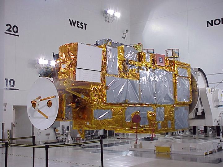
Terra assembled
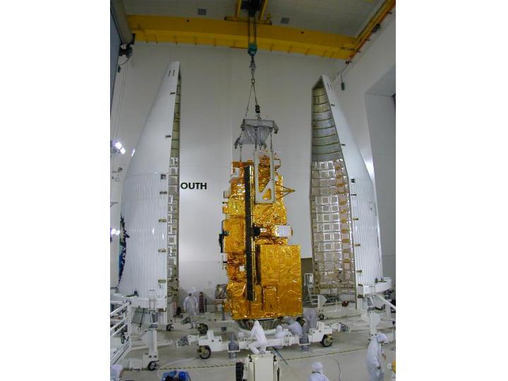
Terra being put in rocket
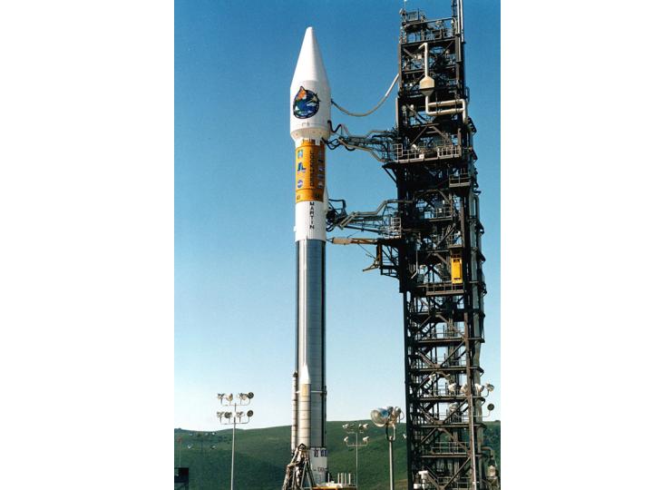
Rocket ready for launch
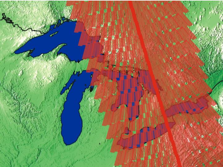
MOPITT scans across the satellite flight track +/- 26.1 deg in 13 secs.
Figure: scan pattern